709-218-7927 The Landfall Garden House 60 Canon Bayley Road Bonavista, Newfoundland CANADA A0C 1B0 |
|---|
Dropping Soil Sieve
This document outlines phases for a wind-powered source of energy to drive mechanical tools. In particular a soil-sieve is proposed as a first example of a mechanical tool.
Soil Sieve - Phase 0
This will be a proof-of-concept and so will be simple, no frills, with an attainable goal. A wind-driven shaft will raise and let fall a mesh sieve containing soil and other material. When the sieve falls, soil will be jolted through the mesh, and after a number of such falls, the remaining material - rocks, pebbles, grass and weeds - can be rejected.
A wooden or steel tower holds the wind rotor and the primary drive shaft. Gearing reduces the speed and increases the torque at the output shaft. The output shaft has a wheel with protruding pegs. Each peg engages the free end of a hinged sieve, raising it over a period of a minute or more, and the free end of the sieve ultimately escapes the peg and falls back to its frame, jolting soil through the sieve.
Goal; Design, Build, and install a wind-powered soil sieve by December 31st 2022.
The system described here consists of an engine and a tool. The engine is a self-contained mobile source of energy (The tower and turbine and horizontal shaft), the tool consists of an optional gear-box and the sieve table and tray.
My idea is that the tool can be any one of a number of applications.
Rotor
The rotor could be a set of flat vanes and a tail fin to point the vanes into the wind, so a horizontal mobile drive shaft; or it could be a wheel with vanes from halved plastic bottles, in which case a vertical fixed-position drive shaft.
The second option, while less efficient in terms of energy, seems to be a simpler design for this proof-of-concept.
I can add extra pop-bottle wheels as long as the vertical shaft has enough length protruding above the tower frame.
A simple wind-gauge would be a ribbon, weighted at the end.
Gearing
I like the idea of a worm-wheel drive mechanism to greatly reduce the gearing and increase the torque. A slow rate of sieving is not important as long as it is continuous. What do I mean?
Suppose that I had installed a sieve when I moved here thirteen hundred days ago. Suppose that the device was so slow that it sieved only half a barrow of soil per day. By now I would have six hundred barrows of sieved soil on hand.
A slow but steady rate of sieving would work its way steadily through an input pile of rubbish. I would have to judge when it was time to start a new load to be sieved, but that might be every half hour throughout the day, or perhaps every hour.
A worm-drive is irreversible.
Your crescent spanner or adjustable wrench is an excellent example of a worm drive; the spanner gap can change slightly, but only if the worm wheel is very loosely housed.
Sieve and Frame
Nothing fancy. I wheelbarrow a load of, say, four shovels of debris to the sieve and toss the debris into the sieve. I place the barrow under the sieve and engage the gears. After an hour or so, the barrow contains soil and can be wheeled away. I manually lift the sieve up, past the vertical, and toss the debris - rocks, pebbles, weeds - outside the footprint of the frame and then return the empty sieve to its starting position.
Perhaps I have several wheel barrows; one receiving sieved soil, one receiving rocks and pebbles, and one used to bring debris to the site.
The frame will need to be high enough for me to shovel debris into the sieve.
The sieve must be light, with walls high enough to prevent tossed rocks bouncing out of the sieve.
Implanted sieves of varying hole size would be nice.
Soil Sieve - Phase 1
No firm definition yet, but will include one or more features:-
(1) A visible rotating pointer that indicates when a preset number of shakes has been given; time to service the sieve.
(2) Method of a horizontal shaker driven by a horizontal impulse.
(3) Ability to add splined rotors to a spline shaft.
(4) Implements - sieve, pump, saw, mixer
(5) Clutch to release power source (turbine)
(6) Bucket belt to load sieve from pile.
(7) Hopper, ore-loaded, to drop a fixed volume of debris onto the sieve tray. Could this be triggered by the next engagement of a peg? Such a mechanism would take energy away from the cycle, but would greatly improve efficiency as the system could run unattended.
(8) No change in weight of the tray indicates all sieving is complete.
(9) Some steel sheet that is laying about can be used to make chutes and hoppers.
(10) Continuous flow so that the retained rocks are shuffled/shaken off the pivoted end of the tray.
(11)
Illustrations
I am no artist.
Basic Idea
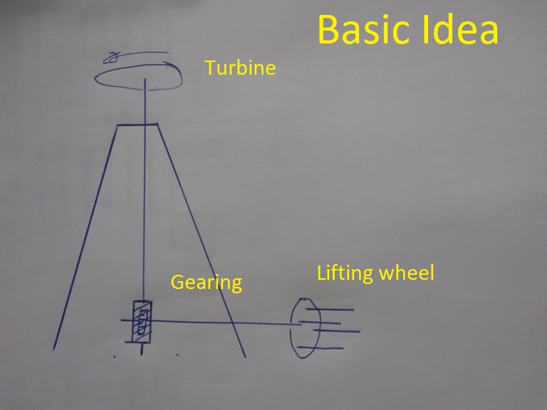
The basic idea is a tower with an omni-directional turbine wheel. The turbine wheel is driven around by the wind.
A vertical shaft carries rotational mechanical energy to a gearing system that drives a three- or four-pronged driving wheel.
The prongs raise one end of a sieve until the sieve escapes its lifting prong and crashes downwards, dislodging soil particles through the mesh.
I would like the two components to be separate modules, so that the turbine tower can be used as an engine on other mechanical devices.
The sieve table then becomes one example of an application. Other applications might make use of the rotational energy directly (mixer, or tumbler) or by a reciprocating mechanism (shaker, or saw)
Turbine
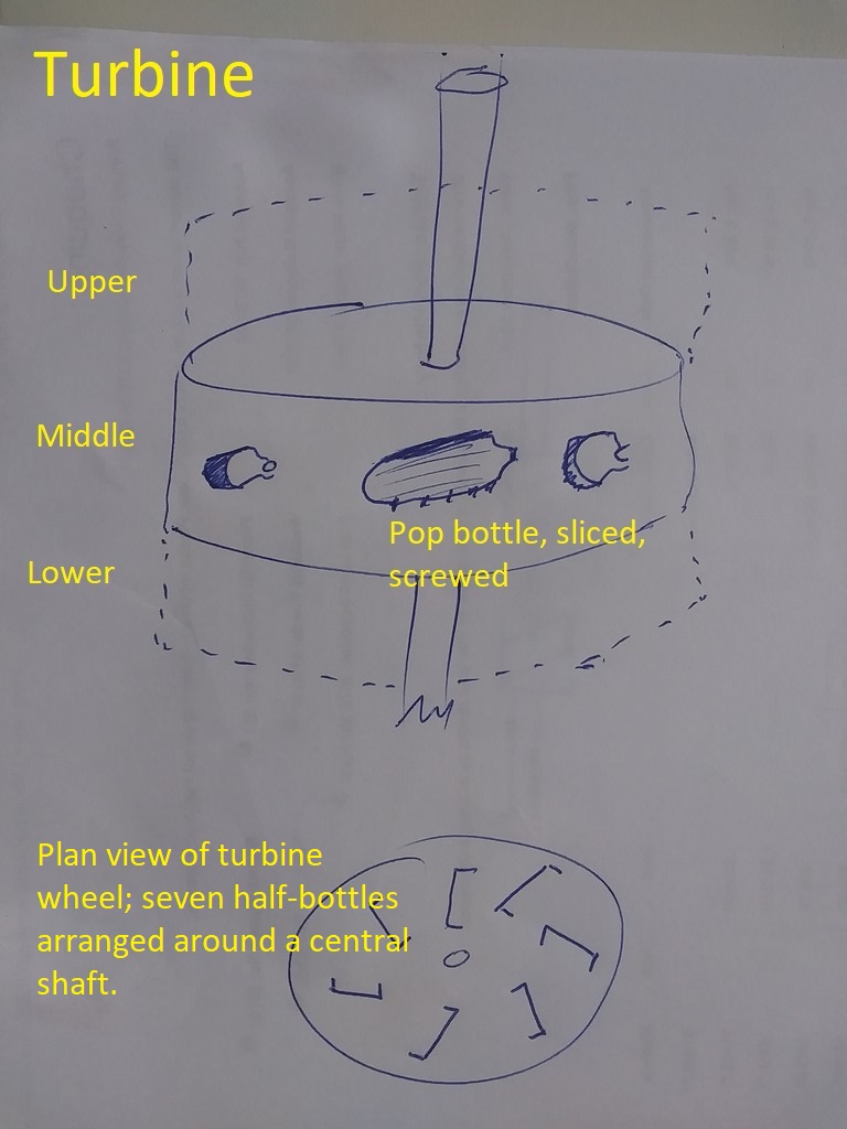
The turbine consists of one or more sets of blades sandwiched between circles of plywood or some other frame.
The blade sets can be added or removed to the vertical shaft.
Each blade offers a collecting area to the wind. Think of two-litre pop plastic bottles sliced lengthwise. The hollow part collects the wind and is driven by the wind.
On the other side of the wheel, the curved outer edge of a sliced bottle offers less resistance to the wind.
An earlier effort (April 2021) failed when the wind stripped the plastic bottles from the screws. This time I shall screw the half-bottles, top and bottom, to their plywood wheel, using strips of plywood (linear washers) to hold the bottles in place.
Some way of disengaging the rotor from the shaft, or else locking the rotor so that it does not ramp up to 3,000 rpm.
Since a worm-drive is irreversible, this might be as simple as locking the horizontal shaft at the lower end of the tower.
Gearing
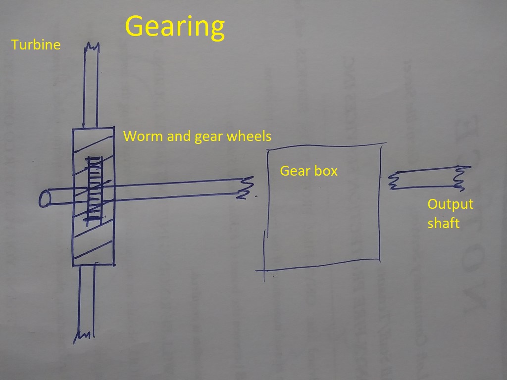
The gearing definition is not complete.
I feel strongly about gearing down to maximize the torque. It matters little to me if the sieve tray is raised and dropped once every five minutes, as long as it is lifted and dropped continuously throughout the day. Soil will be sieved while I perform some other nearby task.
My childhood days with a Meccano set taught me that worm wheels
(a) offer a significantly low gearing.
(b) produce a non-reversible motion. (one-way)
A single-start worm has one spiral groove, a double-start has two grooves, so that in one revolution of the worm screw, two of the grooves pass a fixed point.
If that fixed point is occupied by a pinion wheel or a gear wheel, then two teeth on that target wheel will be advanced. The more spirals (four for example) the more teeth will be advanced.
It follows that a worm with only one spiral groove offers the lowest gear ratio, and that a gear wheel with a large number of teeth offers a low gear ratio.
In the sketch above, my worm wheel is mounted vertically and seems to have two spiral grooves. The gear wheel might have as many as thirty teeth, and is mounted to convert the vertical rotation of the worm wheel axis to a horizontal rotation.
I have drawn a rectangle for the gearing mechanism, because this is undefined. Low-resistance (low friction) is called for to maximize the energy transmitted from the turbine to the sieve tray.
The gearing might be chain-driven, direct drive, or whatever works and is energy efficient. If the wind is sufficiently strong, the gear box might be non-existent, the gearing down by the worm wheel being sufficient to provide torque for the lifting force.
Lifting Mechanism
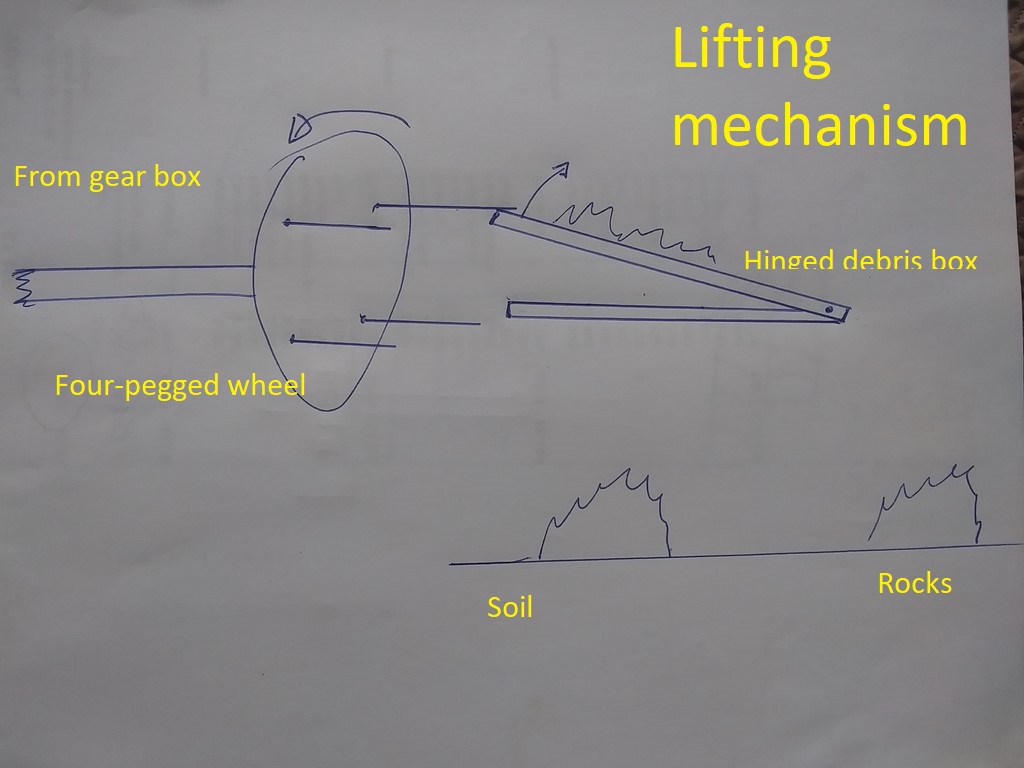
The sketch above shows a four-toothed peg wheel, with each peg mounted strongly enough to lift the loaded sieve.
The action is relatively slow in motion, so the peg does not need to withstand a high impact as much as it needs to endure a steady load.
The sieve tray acts as a lever, and the load force is determined by several factors:-
(a) The mass of debris and soil in the tray
(b) The distance of the soil and debris from the pivot-point of the tray
(c) From the point of view of the sieve tray, the pegs must be angled downward during the contact phase. A peg at right-angles or pointing upwards would hook on, or be hooked on, the tray, whose weight would arrest or snap the peg. We want a peg that allows the sieve to slip off the end of the peg.
(d)
The pegged wheel rotates, with a peg engaging the sieve tray.
As the peg moves upwards it brings the tray with it, until such time as the peg is rotated away from the tray, at which time the tray escapes to fall back to the table under gravity.
Thus we need a peg-wheel with only a few pegs, so that the ray falling from the peg does not impact the next peg on the wheel. Visualize a peg wheel with only one peg - not a problem. Two pegs - still no problem. Three pegs - probably not a problem. Fifty pegs - definitely a problem.
The tray's impact with the table causes soil particles to bounce and shake through the mesh to a collector (perhaps just the ground below).
The tray should be re-loaded in time for the next peg to collect the tray, so as not to waste captured energy..
The Table
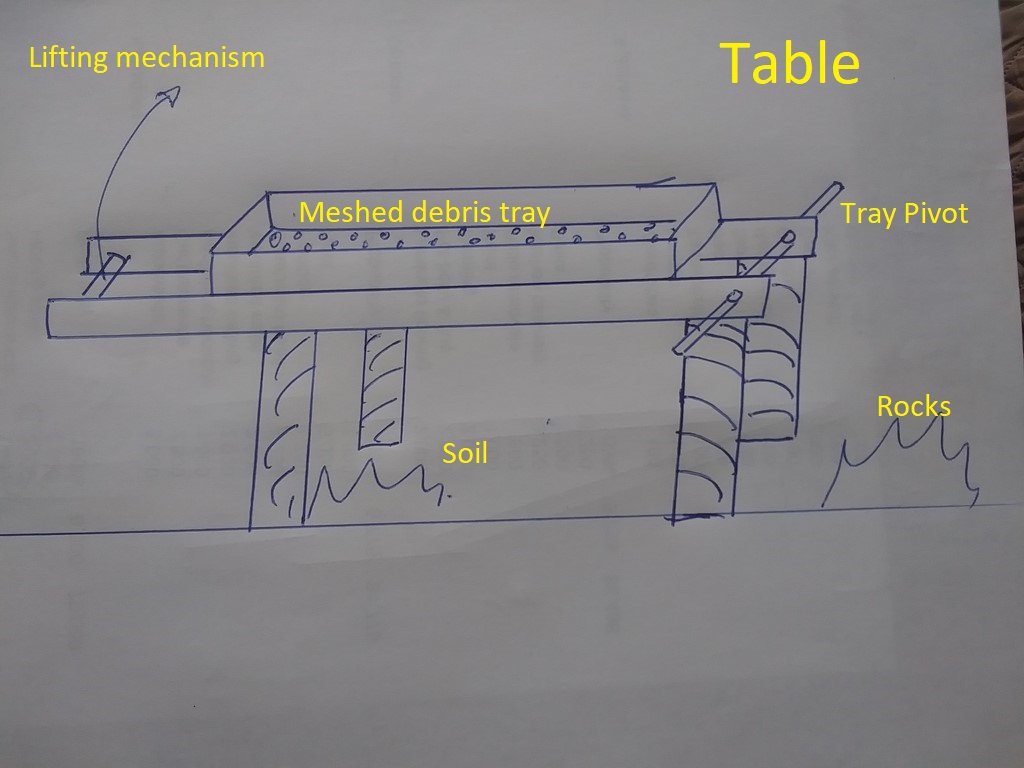
The table needs be robust, as it will receive impacts from the tray pivoted sieve tray.
The lifting mechanism engages a handle at the end of the tray opposite the tray pivot. The handle would allow the sieve to be lifted manually. With a dry load of little debris, manual sieving might be faster than automated sieving.
Mixing grass clippings and sawdust through the sieve might be a good example. Mixing sieved soil, grass clippings and sawdust through the sieve might be a better example. This would allow us to produce the input to a compost pile in place.
When a tray of debris has been sieved, the tray can be rotated around the tray pivot through about 120º and the debris dropped/tossed onto a reject pile beyond the table.
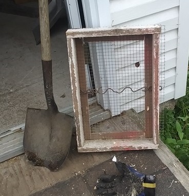
Especially for Phase 0 - the proof of concept - the sieve tray need not be large. I made this tray in 2019 to be a hand-held solution to a problem that grew in size. The frame is heavy wood (all that I had at that time) and the mesh is 1cm, I think (all that I had at that time). This sieve tray would take at most two shovels of debris.
The sieve tray itself is slightly smaller in area than the table. The sieve tray sits in the table and is held in place by gravity.
The sieving tray is a three-sided affair with one end missing, or at best, a slight batten to preserve its shape.
The mesh is fastened to the underside of the three arms, and the arms must be of the lightest construction possible, because energy spent lifting the sieve tray is energy not expended on sieving soil.
In a later phase I anticipate a set of sieves with different sizes of mesh.
I will pick out rocks by hand at the time the sieve is loaded - rocks are fist-sized chunks of debris.
The lifting tray is similar in appearance and construction to the sieving tray, but slightly larger to hold the sieving tray.
The open end of the sieving tray rests on the pivot axle of the lifting tray, and the other end of the sieving tray rests on two triangular brackets, positioned higher than the pivot axle, and so giving a slight downward gradient towards the open end of the sieving tray.
In theory each percussion adds a slight horizontal component of motion to the debris which will travel to, and drop off the end of the sieve.
The other end of the lifting tray extends beyond the support for the sieve tray, and includes a handle that makes it possible to operate the sieve manually on windless days. The handle engages the hooked wheel on days when the energy source is suitable.
The table itself is constructed as a rectangle of 2x4 timber on braced legs of 2x4 timber.
The table should be high enough (at least 24 inches) to receive a wheelbarrow or wheeled trolley underneath; a second wheeled trolley might receive the rock debris off the end of the sieve.
Both locations could be served by a cloth or similar material chute to guide output to a specific area.
Ideally both the tower and the table should be light enough to be established in position by a single person. That said, a system with components on wheels would be suitable. (A wheel-barrow type of arrangement, or even a special two-wheeled trolley and make two trips, one trip for each component.
The table could incorporate a 6" skirt or tray below it to collect soil. A skirt would be flexible enough to accommodate a wheelbarrow (height remains at 24") but a tray would add 6" to the table's height. The tray could be as simple sheet of Masonite or ¼" plywood with a transverse slot towards which soil could be pushed manually. A gradual slope towards the slot - away from the debris end - might be assisted by repeated percussions to move soil into the slot.
Goal
Design, Build, and install a wind-powered soil sieve by December 31st 2022.
Measurable Objectives:-
(1) Meet with Reg Faulkner; agree on a basic design for Phase 0; discuss features for Phase 1.
Measure: The meeting takes place; this document is frozen.
(2) Build a turbine wheel and shaft and tower.
Measure: In a wind measured at 20 knots, the vertical shaft rotates, and is robust enough to continue operation for seven days of continuous wind.
The wheel consists of one or more pop-bottle sandwiches.
Two circular sheets (quarter-inch?) of plywood sandwich as many split two-litre pop bottles as can fit.
The pop bottles are bolted into the plywood using strips of plywood front and back so that the wind is less likely to tear the bottles from the bolts - as happened in my first version of a turbine.
Each sandwich wheel can be dropped onto the shaft and fixed to the shaft.
A spline shaft is probably too difficult, but a collar like a Meccano Heavy Duty Brass Bush wheel should do the trick.
(3) Measure the horsepower of the turbine wheel vertical shaft.
Measure: A cotton string (through a pulley) raising a fixed weight (two pounds) through a fixed height (five feet) in 120 seconds represents 0.0002 horsepower.
2.00 |
Pounds |
|---|---|
5.00 |
Feet |
120.00 |
Seconds |
0.08 |
foot-pound-seconds |
0.0002 |
Horsepower |
My calculation should be checked by someone else.
A benchmark table for a set of at least three masses and two lengths of lift will be established.
This same table will be used to measure lift at various stages along any drive shaft, so that we gain a measure of energy-loss as a gear-box is introduced, or a change of direction is employed.
Power from a vertical shaft is measured via a cotton string and small pulley. This will reduce apparent power output, but we will be erring on the low side, that is, a conservative estimate.
Better data can be obtained by a raised tower; although the real system might use just five feet, we can always test using a ten- or fifteen-foot height.
(4) Worm wheel drive to horizontal shaft.
Measure: In a wind measured at 20 knots, the vertical shaft rotates.
(5) Measure the horsepower of the horizontal shaft.
Measure: A cotton string (through a pulley) raising a fixed weight (two pounds) through a fixed height (five feet) in 120 seconds represents 0.0002 horsepower.
(6) Build a dummy hinged tray.
Measure: The height at which sieved soil drops through is at least one foot.
Construction of the table and tray can begin immediately. The tray will be a version of the stroller-sieve I played with two years ago. I should be able to evaluate sizes and positions and loads by manual operation of the peg handle. Too I should be able to measure the work (foot-pounds) required to raise the sieve tray a given height with a given load in a given position.
(7) Measure the rate of percussion of the tray for a variety of loads at a fixed distance from the pivot.
Measure:
(8) Measure the count of percussions required to sieve a load of pre-sieved material. (100% completion rate)
Measure:
(9) Build the table.
Measure:
(10) Assemble and connect all components (no gear box at this stage)
Measure:
(11) Measure throughput for three different types of material (100% soil, 30% rocks, clumps of sod and weeds)
Measure:
Monday, August 15, 2022
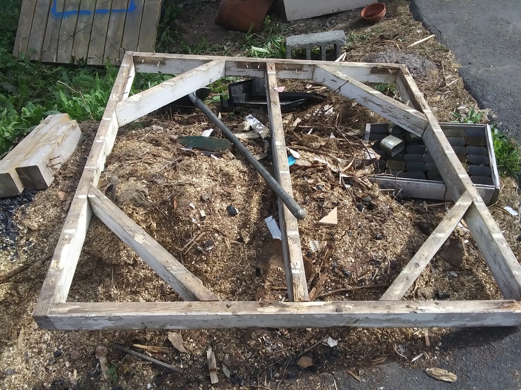
Yesterday I engaged Spence to knock apart a collection of gates and fences. This rugged frame is from a large garden gate.
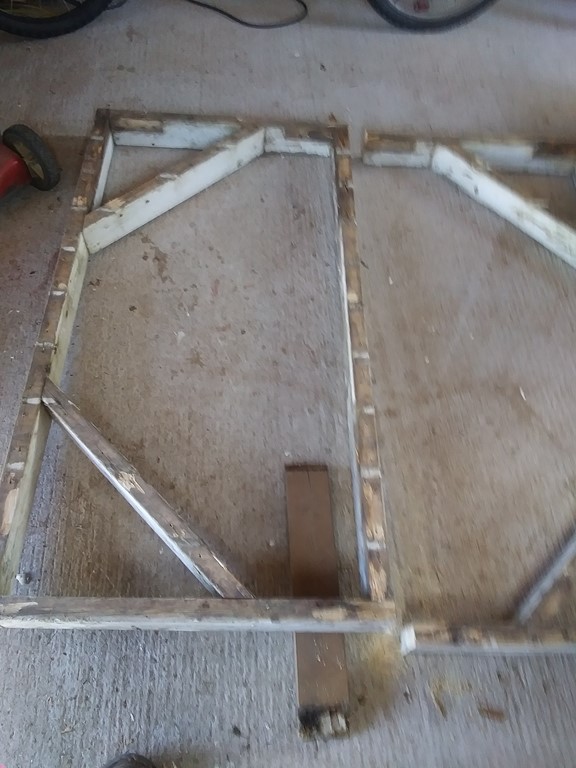
I reasoned that two quick cuts would provide me with a heavy, sturdy frame for the table top. This proved to be the case.
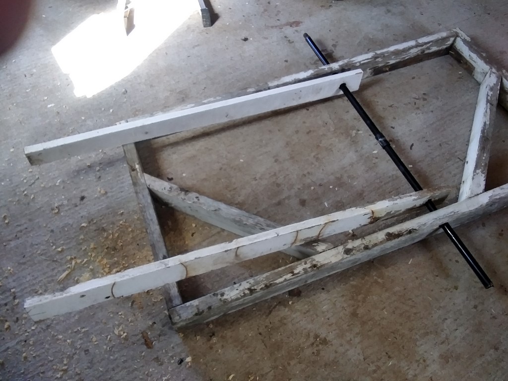
Thus emboldened I grabbed two palings that were lying around from yesterday, and augured holes in the palings and the frame. An old mop handle provides an axle for the pivot.
Of course, it isn't painted yet, nor does it have legs. Or mesh and so on, but it is a start.
Tuesday, August 16, 2022
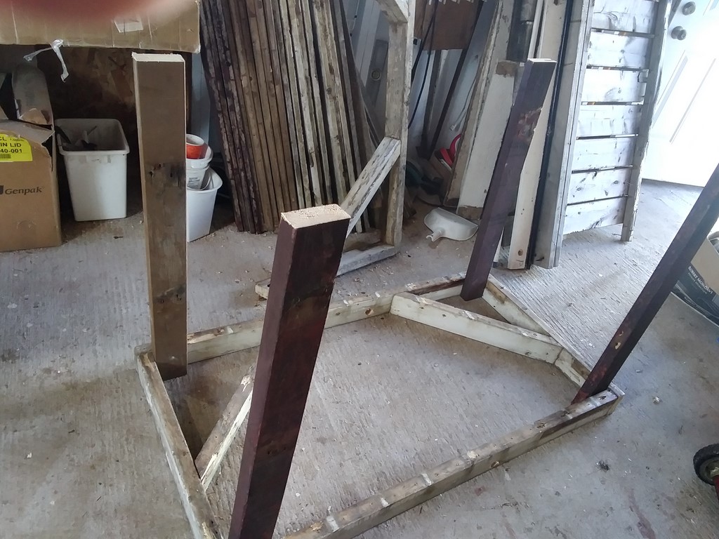
I have removed dead screws and nails and trimmed to 36" lengths four chunks of 2x4 from the old picnic benches.
Each leg is tacked in place with just two 3" wood screws. Handle with care.
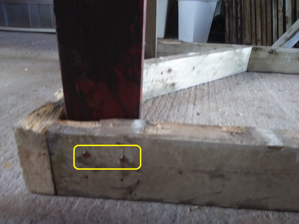
A traditionally poor shot of the two screws holding this leg.
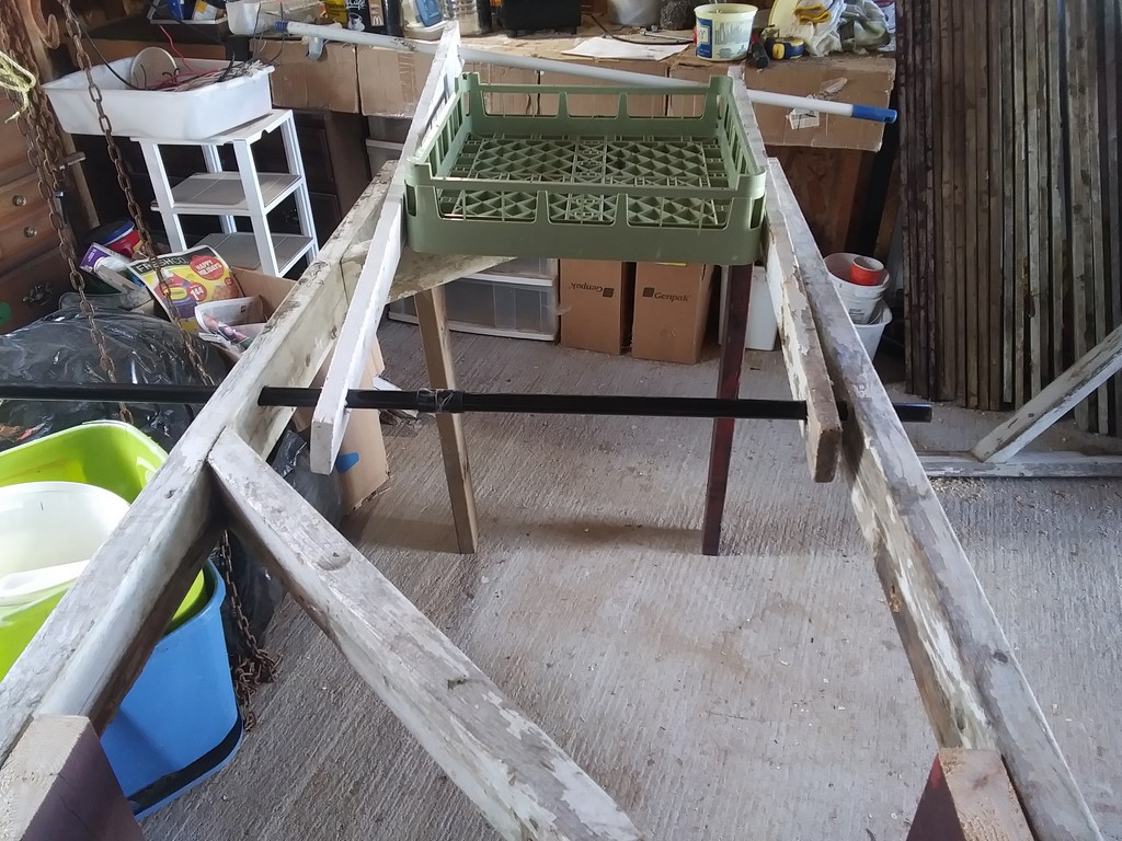
Standing on its four shaky legs, with the shaker handles in place.
The black pole is the pivot rod (axle) and the lop-sided white handle is the handle for manual sieving. Lop-sided because a diagonal brace obstructs the final descent.
The green tray is there only to indicate where the mesh will be.
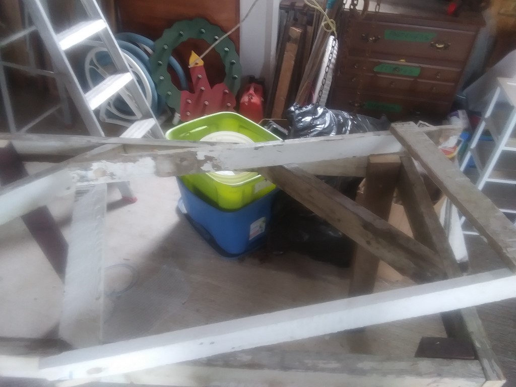
The sieve tray. The ¼" mesh does not show well in this photo.
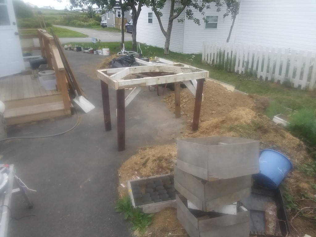
The table, somewhat braced, ready for its first trial. To the right of the table is a pile of rubble to be sieved, to the foreground of that a pile of sawdust that is riddled with roots and bark. Behind the table are a half-dozen bags of grass clippings to be composted.
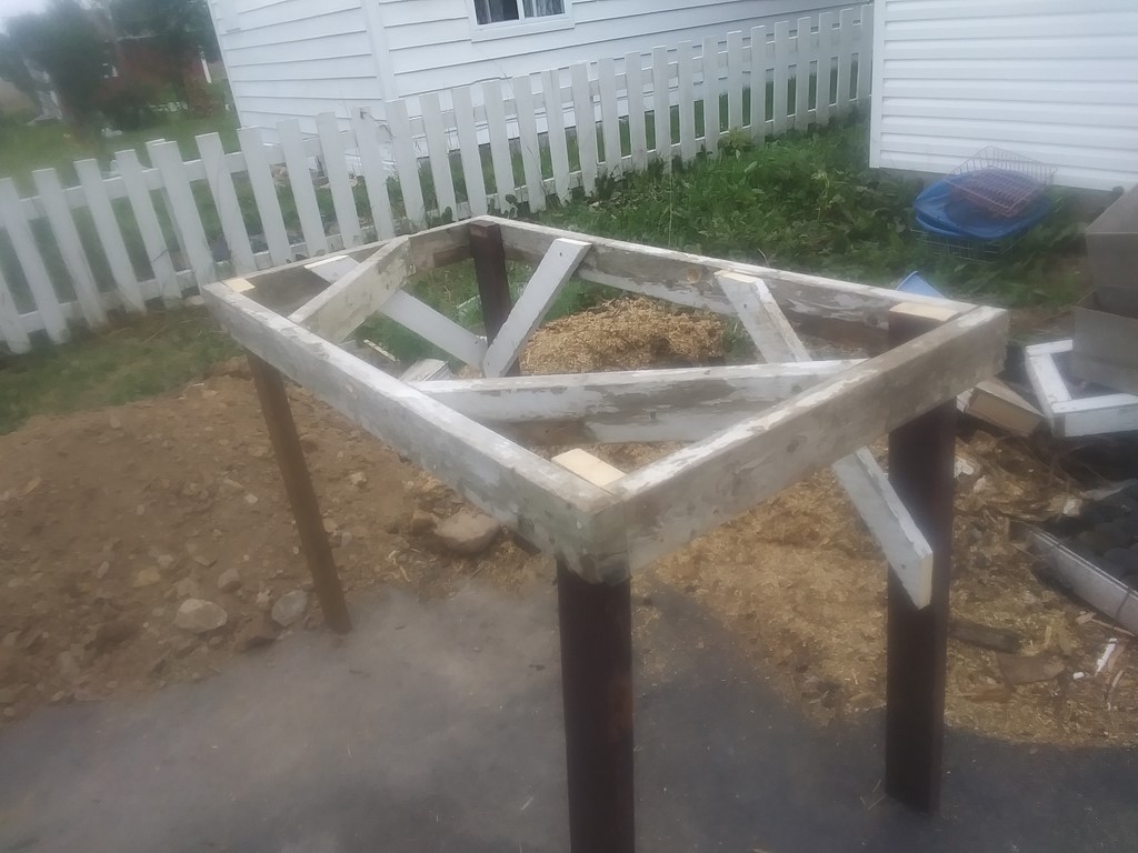
Another view of the table with the piles of rubble and sawdust.
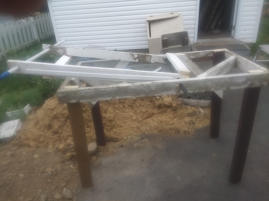
The sieve tray in place. The white handle waits to be gripped and raised and dropped.
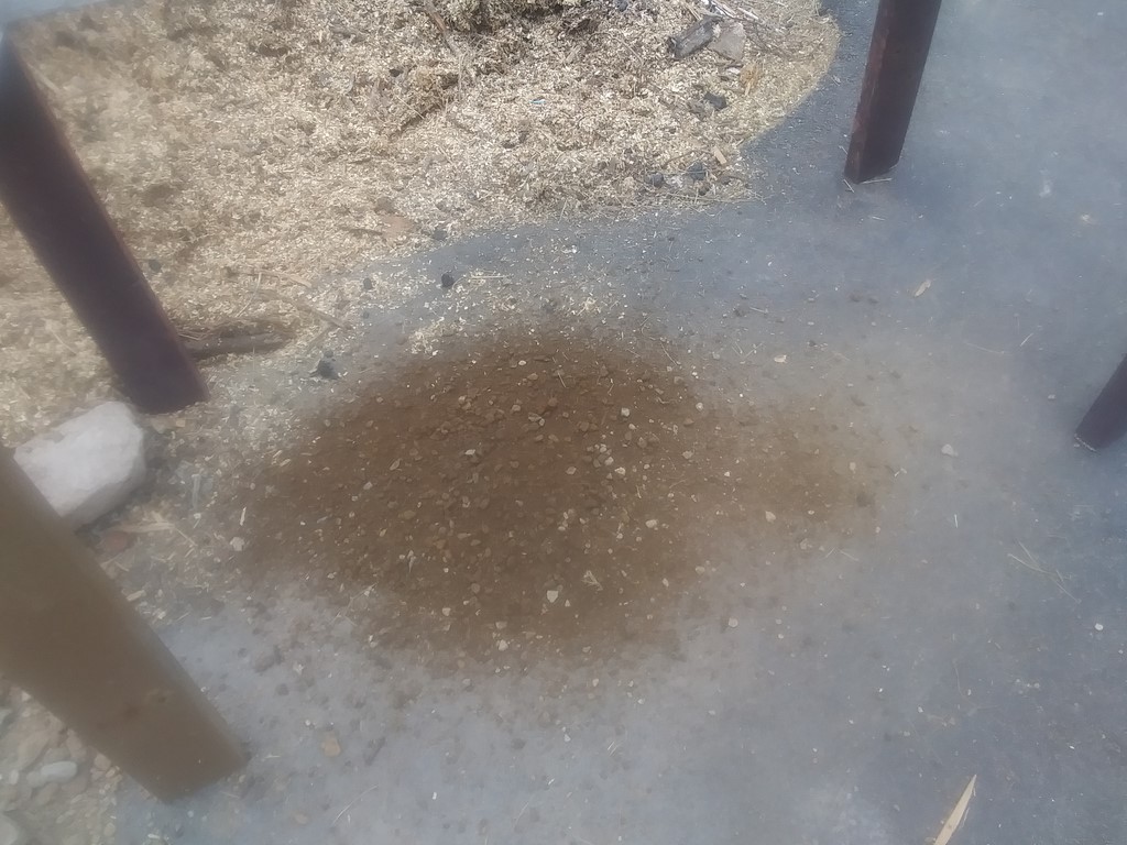
The first shovel of soil drops through the sieve to the ground below ...
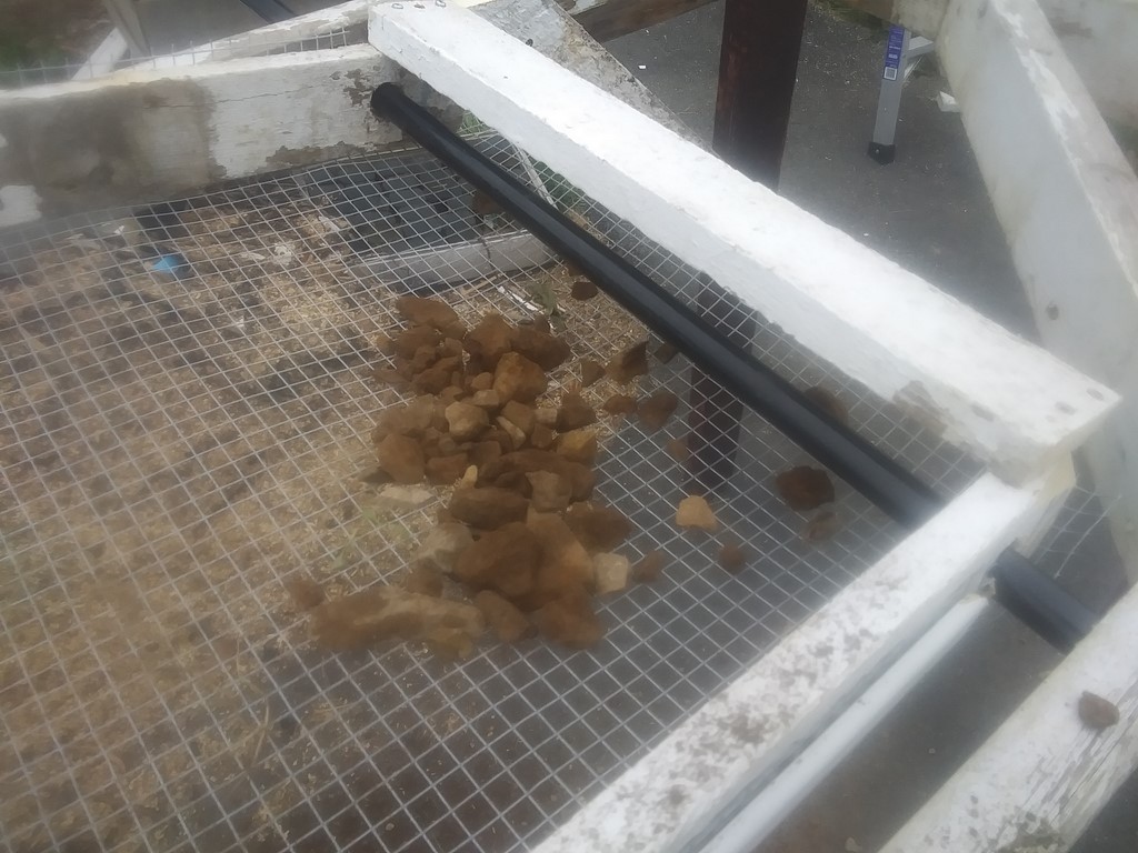
... leaving behind a small pile of rocks and pebbles.
The un-hemmed mesh curls up at the end; it must curl downwards and empty onto a chute (below)
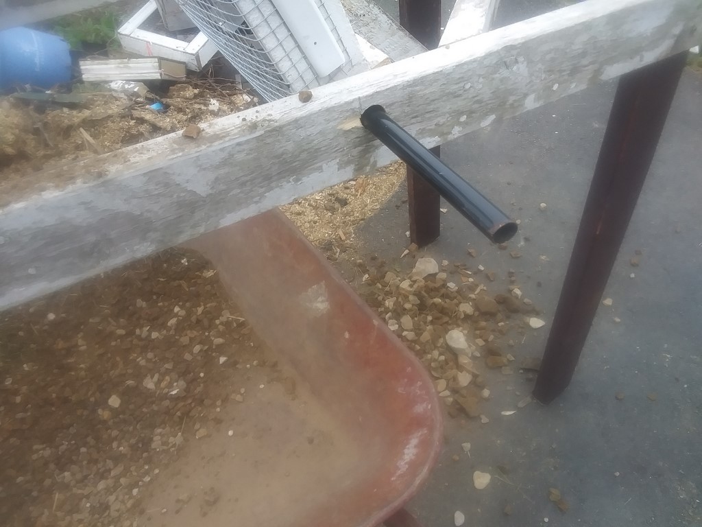
I have tipped the sieve tray to empty out its load of pebbles. These pebbles should fall into a chute and hence into a wheeled trolley to cart the debris across the street to David's driveway.
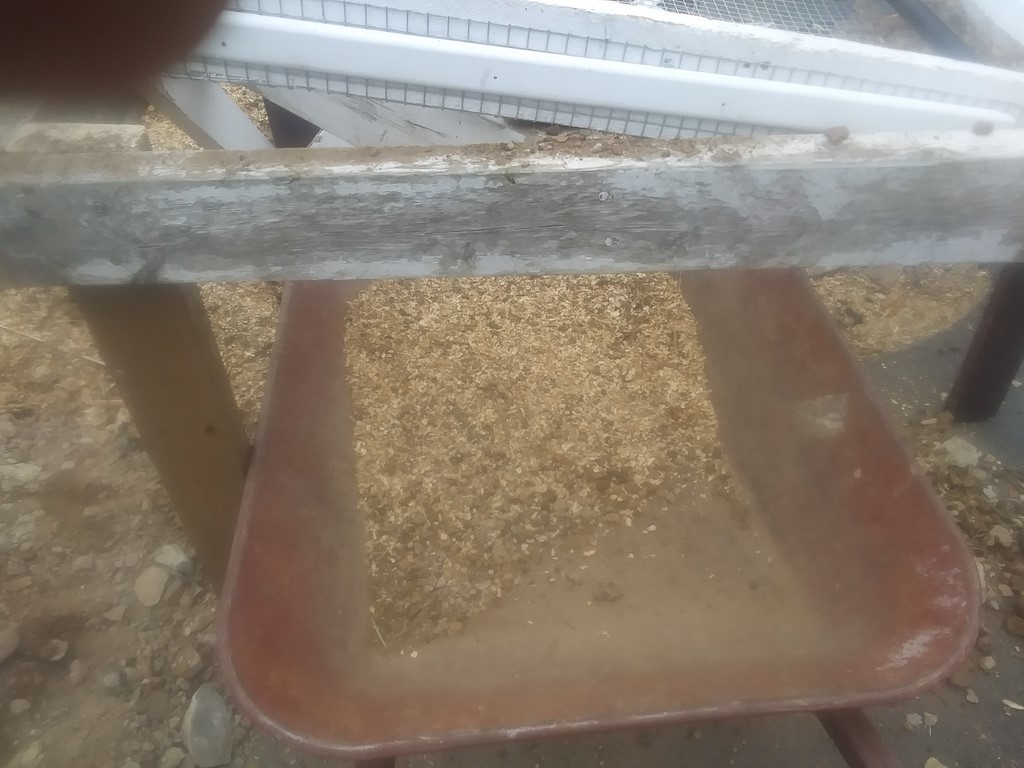
Sawdust goes through well ...
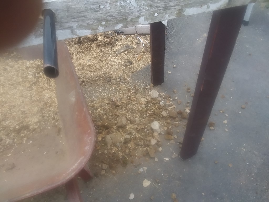
... but owing to the bad slope of the sieve, leaves too much material with debris.
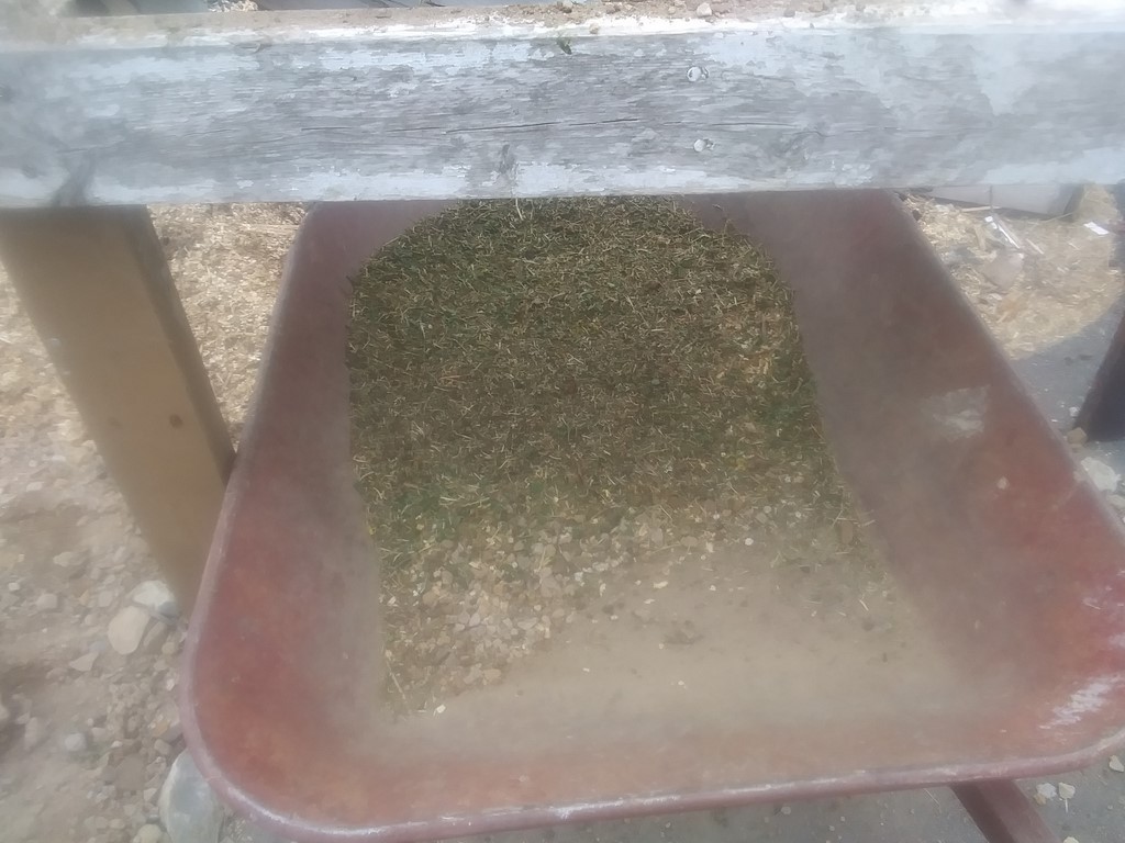
Grass too falls through, but not enough.
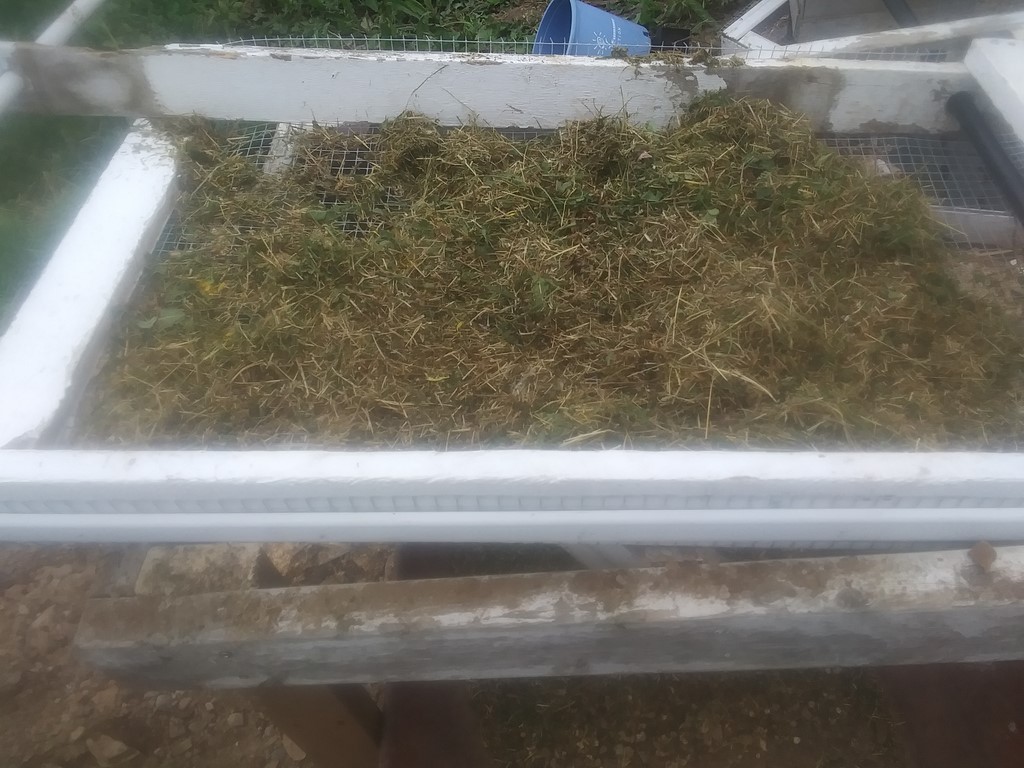
Today's grass is too sticky, and does not want to drop through the sieve. No matter. I can add grass clippings at will.
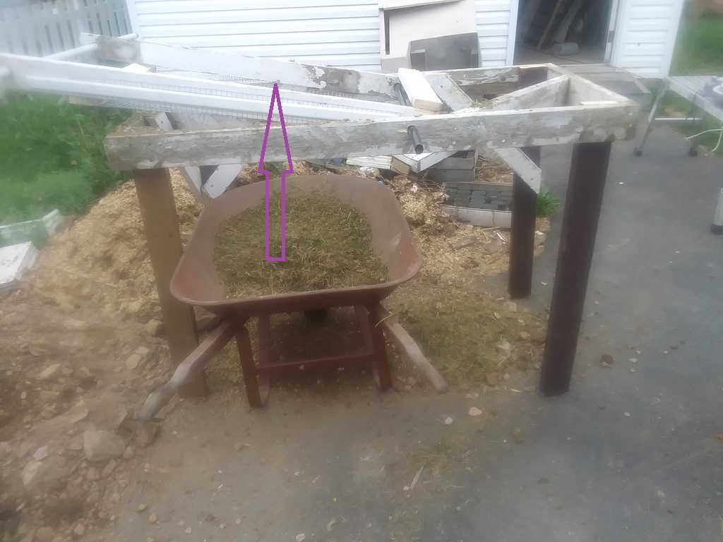

The gradient of the sieve is wrong. Just visible is a second diagonal brace that obstructs the sieve. If I remove the brace, then the sieve will lay flatter and in theory the passage of material will be slowed so that there is a greater chance of fine material passing through the sieve.
I rather think that in practice the sieve should remain horizontal, with the occasional uplift lending a miniscule factor of horizontal motion. We shall see.
Or better yet, a slight downward gradient towards the handle, so that in manual use the operator can slide material from one end to the other and back again.
Wednesday, August 17, 2022
Today I need a chute to drop rocks into a wheeled cart or barrow.
Or maybe not.
Thursday, August 18, 2022
Below is a sequence of photographs taken every twenty one-inch drops of the sieve.
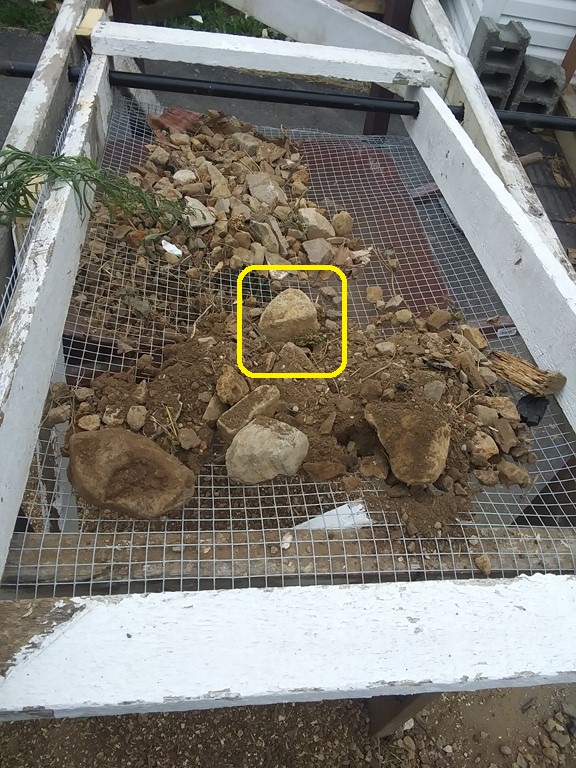
Shakes 0: Keep your eye on the "cube" rock, outlined in yellow.
First I load two shovels of dry clay and rubble at the handle end of the sieve. Roughly half the load drops straight through the sieve as clay.
Above you can see just over one shovel load of debris, so tossing the rubble onto the sieve effects obtains about 50% of the soil with no energy required from the operator (or the wind, or an electric motor)
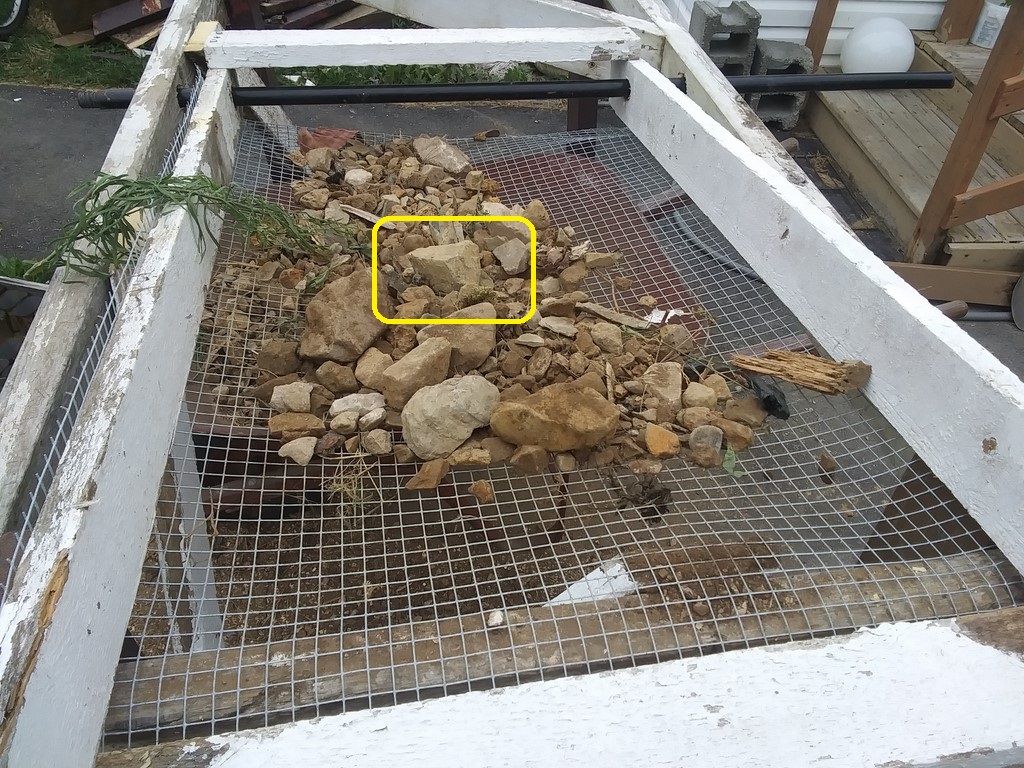
Shakes 20: the new debris is merged with the previous stream and about 80% of the remaining soil has dropped through. I could measure accurately with a plastic bag below the sieve and weigh the soil at each 20 shakes.
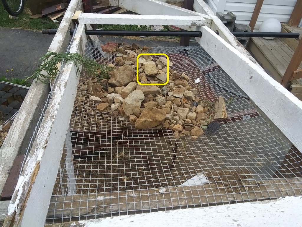
Shakes 40: the debris is moving steadily down the sieve.
At this time I hear the tinkle of a shower of rocks falling into the barrow. Those are the rocks from a previous session/load.
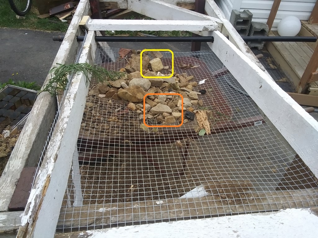
Shakes 60: Keep your eye on the "arrowhead" outlined in orange.
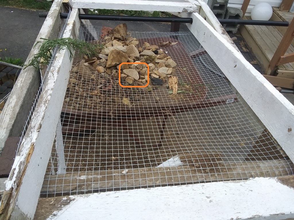
Shakes 80:
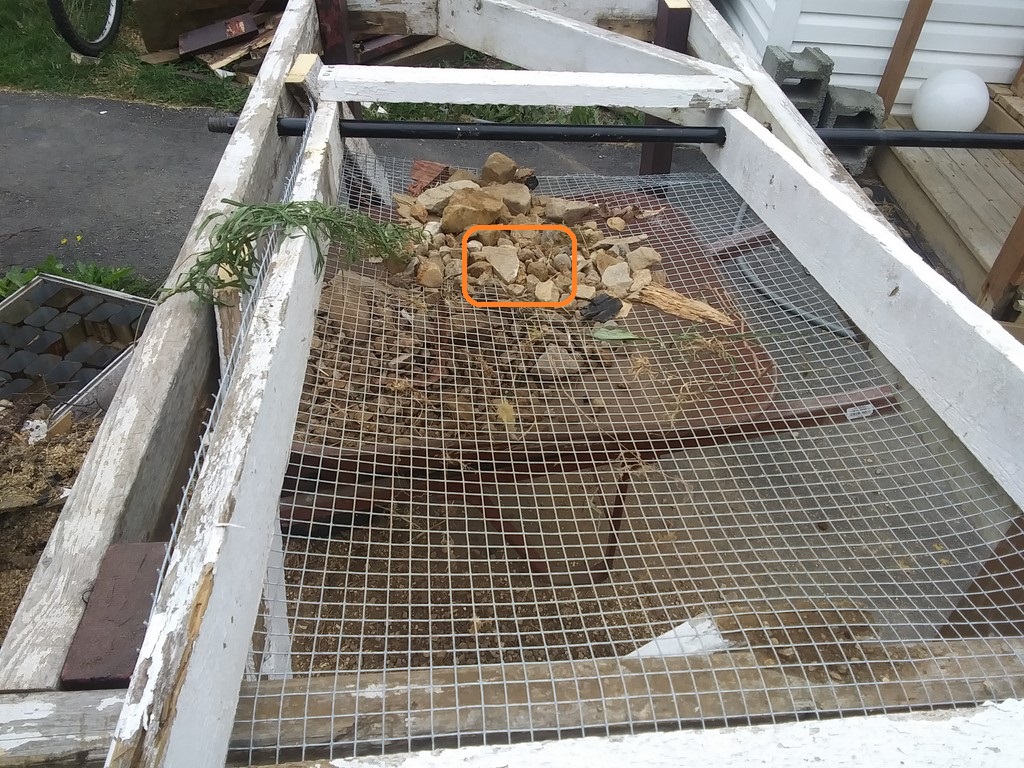
Shakes 100:
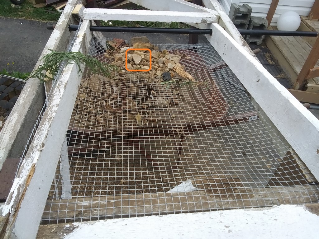
Shakes 120:
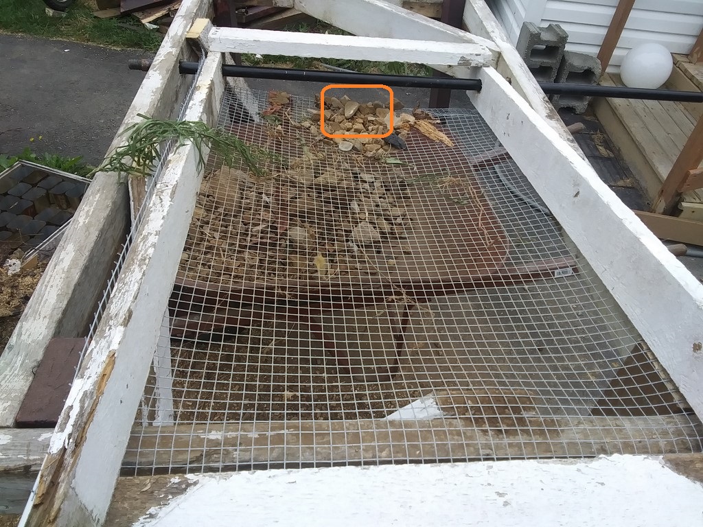
Shakes 140:
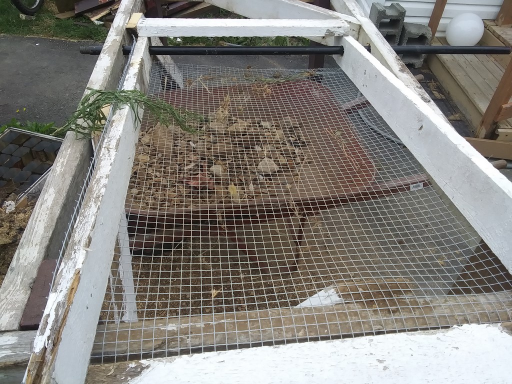
Shakes 160: the sieve is empty, except for a weed that snagged itself on the sieve rim.
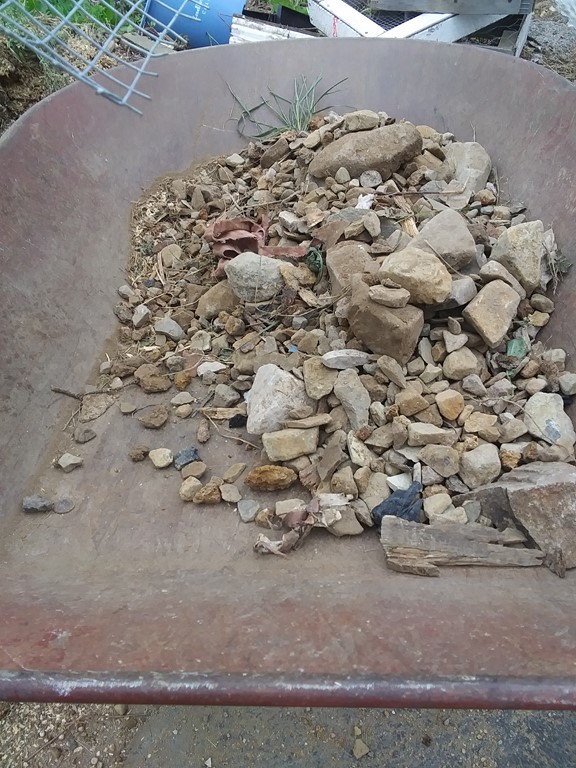
A barrow containing rocks.
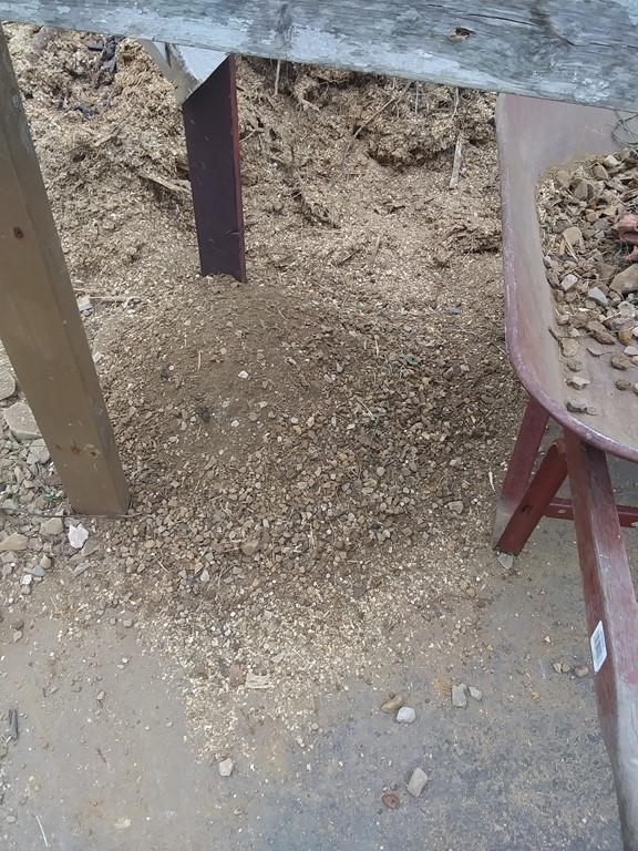
A heap of "soil". This should be falling into another wheeled barrow.
I learned that 160 shakes was needed to process a two-shovel load. Now I think that I could feed one shovel of debris to the top of the shaker sieve each 20 shakes, so if a wind powered engine can shake the sieve once every ten seconds, then 200 seconds will process a shovel of debris in a continuous flow, which makes me think about a bucket chain loading the sieve from an input pile!
For my next test I will use two people, one shaking the tray and counting, calling out every twenty shakes for another shovel full to be loaded.
Friday, August 19, 2022
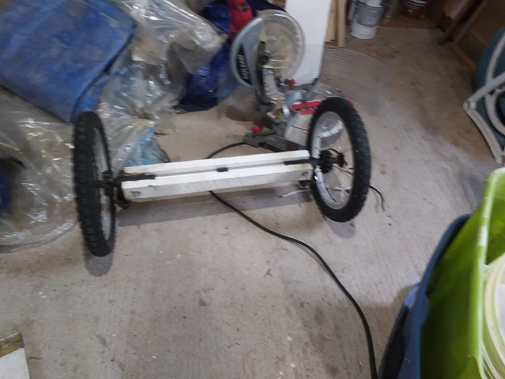
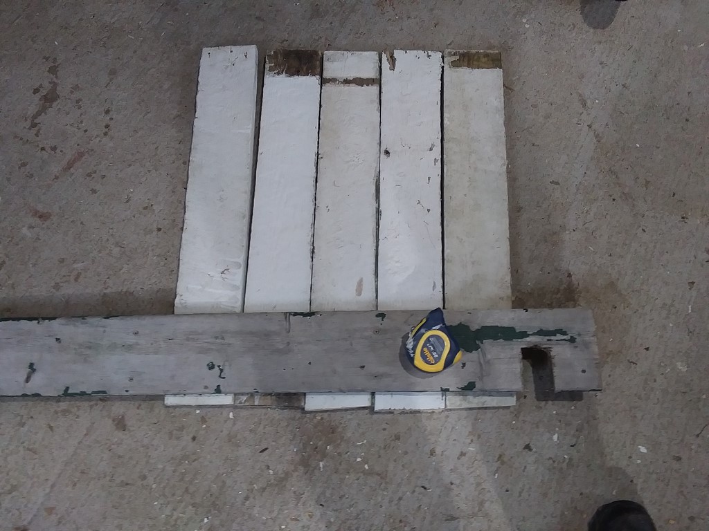
The stroller axle sandwiched between two stout palings. Four long wood screws is all.
I started then abandoned the idea of building a box out of palings when I realized that I had two or three shallow-walled plastic trays.
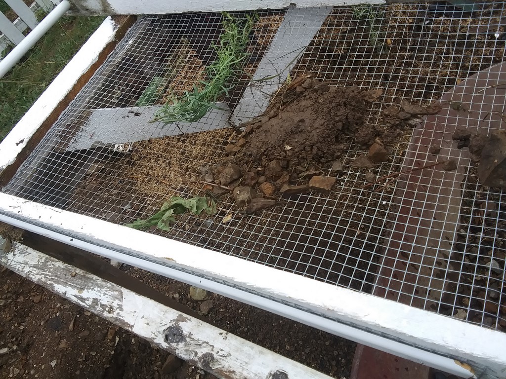
Overnight rain means a shovelful is of mud, and it does not break up and fall through the sieve. I should organize a waterproof cover for the next day's material to be sieved.
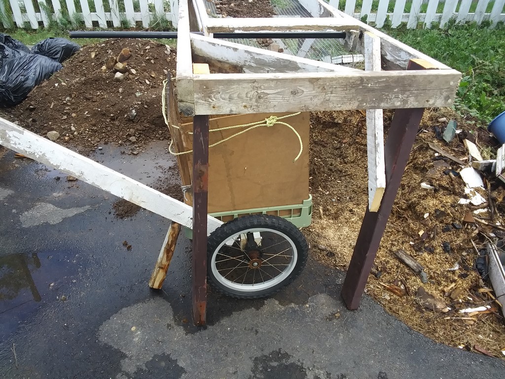
My wheeled-barrow waiting to be loaded with rocks and pebble debris.
The walls are 18" squares of Masonite that used to be my chimney-wall.
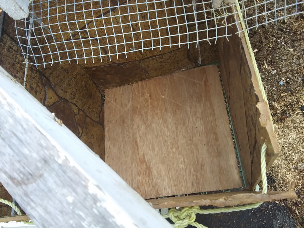
The drop-in base is an 18" square piece of ¼" plywood.
That should be enough to hold a load of pebbles.
Nylon rope binds the top of the four walls. Easy to dismantle and store.
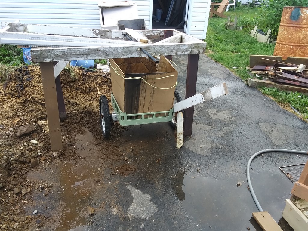
A single handle, poorly attached, but a handle. A short paling props up the bin. Either I fix swinging legs, or I build a cradle to dock the barrow under the sieve.
Sunday, August 21, 2022
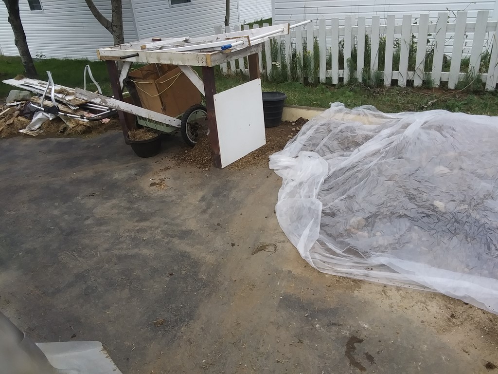
I have placed two guard sheets to contain drift from soil and rocks. The machine is re-sited so as not to block access to the shed. Debris enters from the right, uphill slope, and rocks are ejected from the left, towards the end of the driveway.
I hope too that the path we use alongside the deck will be free from dust and wet clay, less crud tramped into the house.
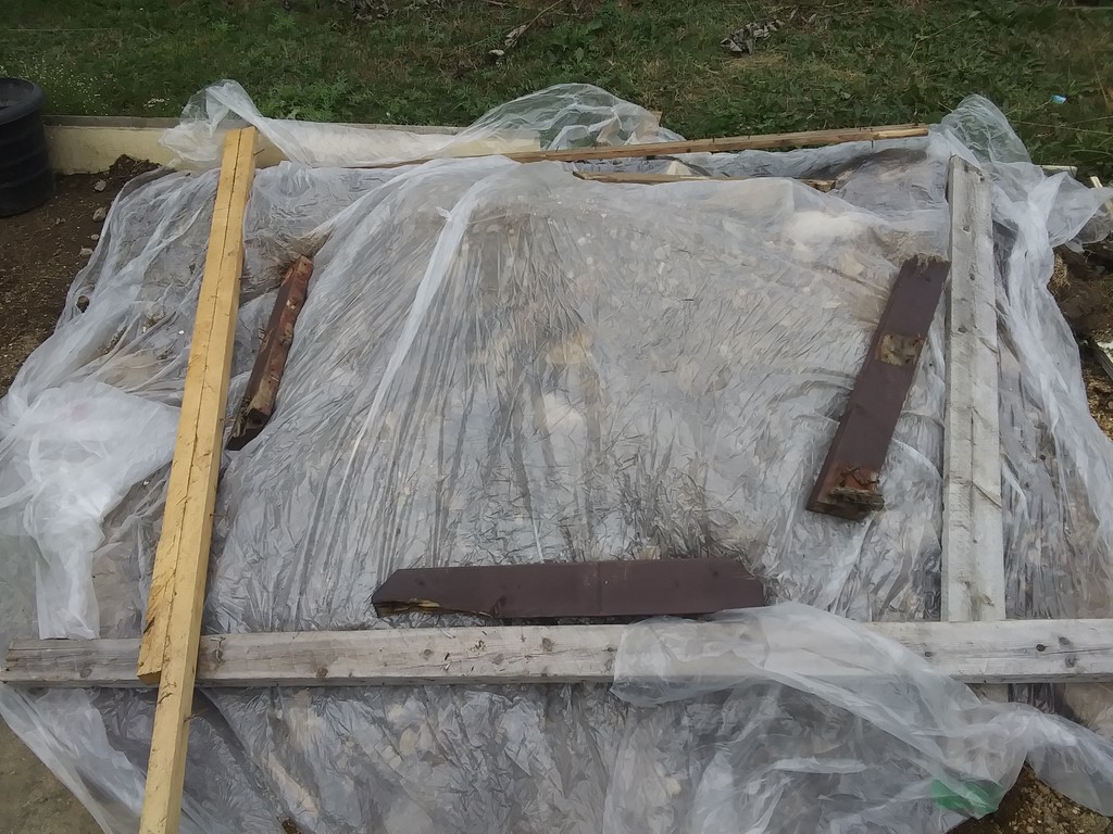
I have covered my debris sheet with plastic, hoping that there will be heat trapped inside to boil off water, air gap enough to blow out the vapor, and that the planks will stop the sheet from blowing into the street.
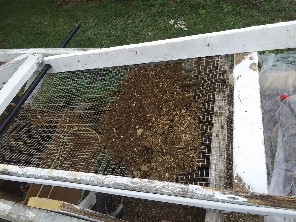
A shovel of debris loaded at the top of the sheet ...
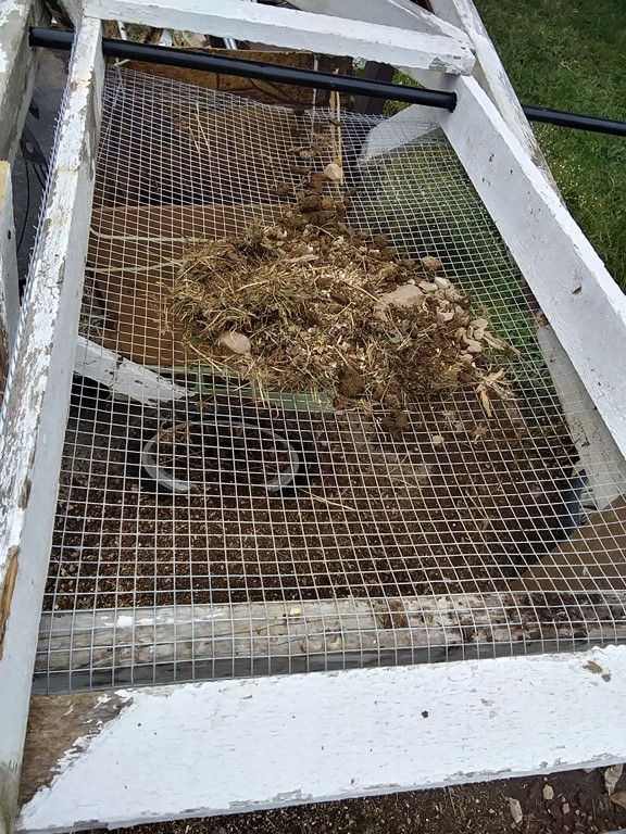
... turns into a narrow stream of rocks where the far end sags, and a narrowed stream of debris approaching that end.
How can I keep the debris spread out but the rock stream narrow?
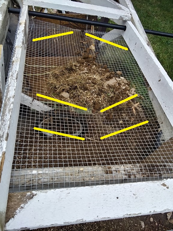
A pair of spreader-baffles attached to the mesh at the uphill end, and a collector baffle immediately before the drop-off.
I dream these things up, but looking ahead to a wind-powered source of energy, every bit of resistance to flow of material is another dissipation of the energy available for moving material through the system.
Instead of baffles atop the mesh, spreading the material, I may be better served by the same mass of baffles used UNDER the mesh to inhibit sagging at the top end.
Tuesday, August 23, 2022
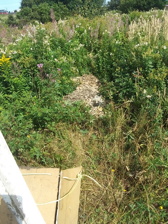
I used the one-handled trial barrow and took a ¼ box of rocks across the street to DF's. I am building a rocky path into the wilderness. As long as that barrow works, I see no reason to enhance it.
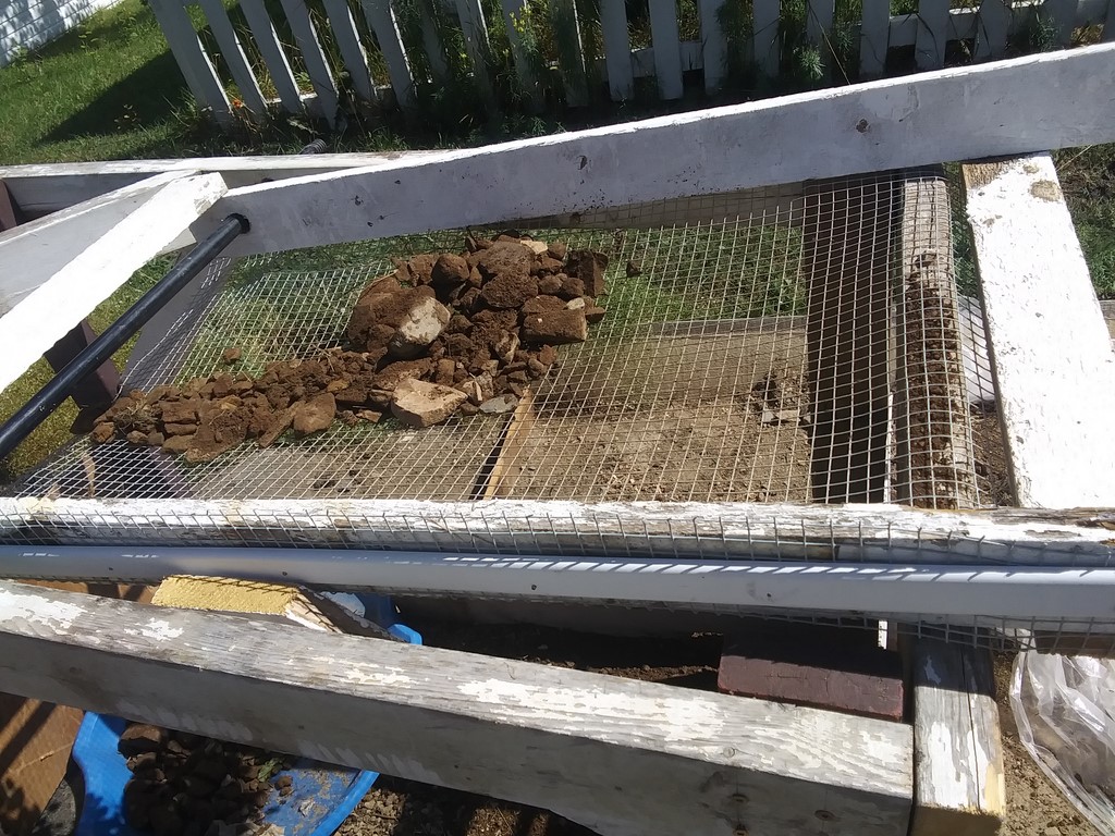
The sieve is about to receive the next shovel of material. Rocks from the previous shovel(s) are still moving down the mesh.
Theory is that these residual rocks act as a rolling road-block, slowing the movement of the next shovel of material, giving more time for soil to shake through the sieve.
That is, the residual rocks act as a speed-regulator for the lateral movement of the next load, improving the soil-per-shovel yield.
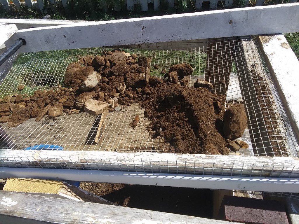
Seconds later the next shovel of material is in place, and will be held up by the residual rocks.
Look at the rich dark colour of the dampened soil. This is from under Danny's house; it is not composted material, nor is it mixed with Tom's debris.

I have left my prototype barrow at the foot of the driveway, thinking that a Book Bin, a Barrow, and a sign "Greaves's Groves" might cause more people to stop on their way out of town. I figure that Marty and Irene will discuss their visit if it was the last thing they saw in Bonavista on their 3½-hour drive back to St John's (Goulds)
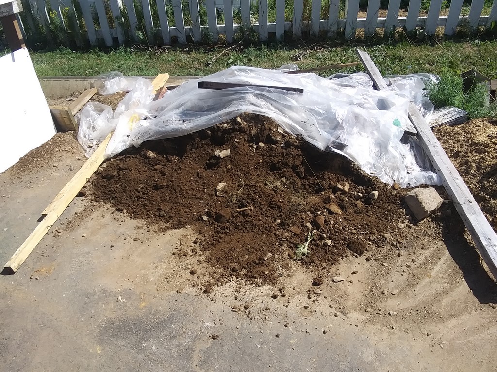
I am spreading the front edge of the rain-soaked material to dry for an hour or so before sieving it.
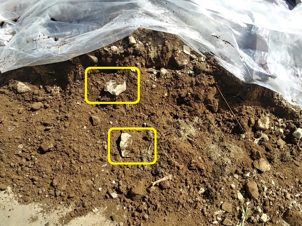
I will hand-pick larger rocks for the rockery.
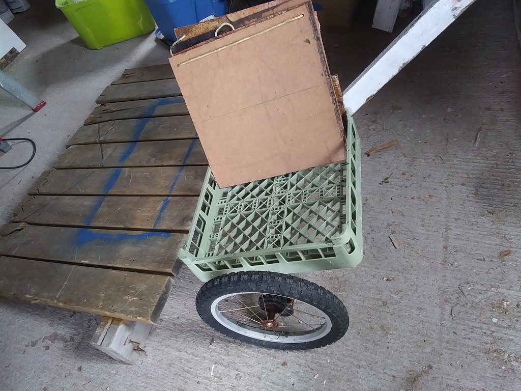
My wheeled-barrow box, overloaded, collapsed when I tipped it on its second trip.
No matter. I have plans for a wheeled platform with two handles; the handlebar will be a crank/winch with which I can drag a "dumpster box" onto the base; the cable will hold the box in place and then I can release and tip it.
Any size boxes that I care to make.
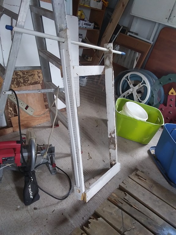
Tomorrow, rain through it might, I want to quickly make a second sieve, four pieces of paling, four bored holes, and a piece of chicken-mesh rather than my ½-cm mesh. With that I can sieve the sawdust-and-rebar, and perhaps do something with clods of earth.
Thursday, August 25, 2022
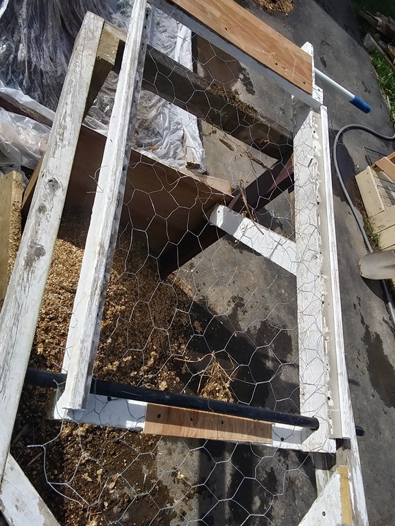
Here is the chicken-mesh sieve; same structure and size as the first sieve. Pull out the rods, switch sieves, push in the rods, and GO!
I ran five shovels through; the sieving is fast, and it makes no sense to dance the bark and twigs to the end - just raise the sieve and chute them out.
Note that I mixed some shavings with soil; no matter. It is, as we say in the trade, all grist for the mill.
Friday, August 26, 2022
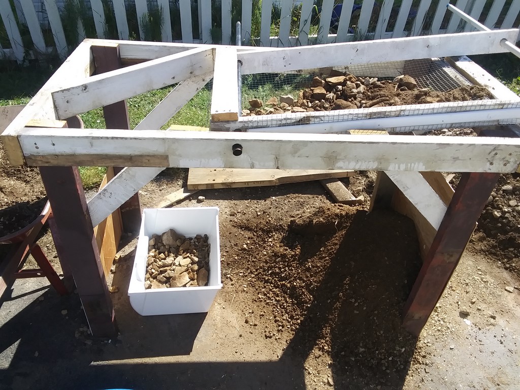
I have replaced the large circular tray with a refrigerator vegetable crisper drawer. This drawer is a large enough target for the end-of-sieve.
I am of the conclusion that this shaker method is a dead-end.
Better would be a rotary sieve:-
This drum is powered by an electric motor (LHS) and is slightly inclined left to right.
Toss the potatoes and stems and roots and soil in the left hand end, start the motor, and ...
... spuds drop out at the far end.
Advantages:-
(1) Quieter; no jarring bang-bang-bang
(2) Can be used to separate sawdust from its barks, twigs, roots and the like
(3) Can be used as a mixer - replace the sieve with solid material and mix soil, grass clippings, hay and sawdust, producing an output stream of bedding suitable for next year's garden.
(4) Different grades of sieve can cope with different sizes of rocks.
(5) A water-spray would reclaim soil from rocks.
(6)
The machine shown above seems to have two sieves, but I think that I would be happy with a machine into which I can toss material, and which delivers just two streams of material as output.
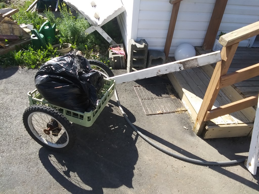
The trolley in use, lugging the second load of grass clippings. I can easily fit two bags in the cradle.
The one-handle system has the advantage that the other hand can be used to carry a shovel or some other implement.
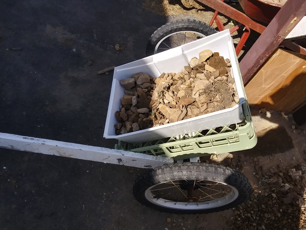
A bucket of rocks heading over to David's place.
Monday, August 29, 2022
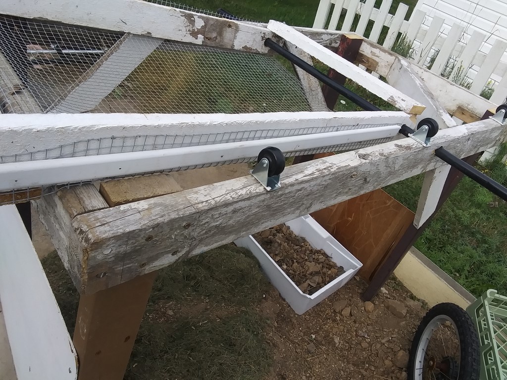
I bought six small castors at $3 each to trial a trommel
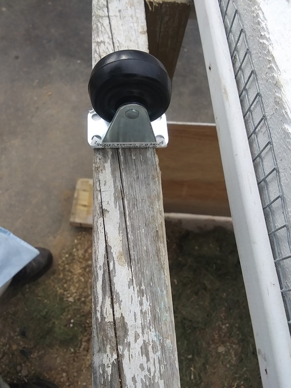
The trunions are so small that I will need to build a platform that holds the rollers, that platform sitting on/in my table structure.
Tuesday, August 30, 2022
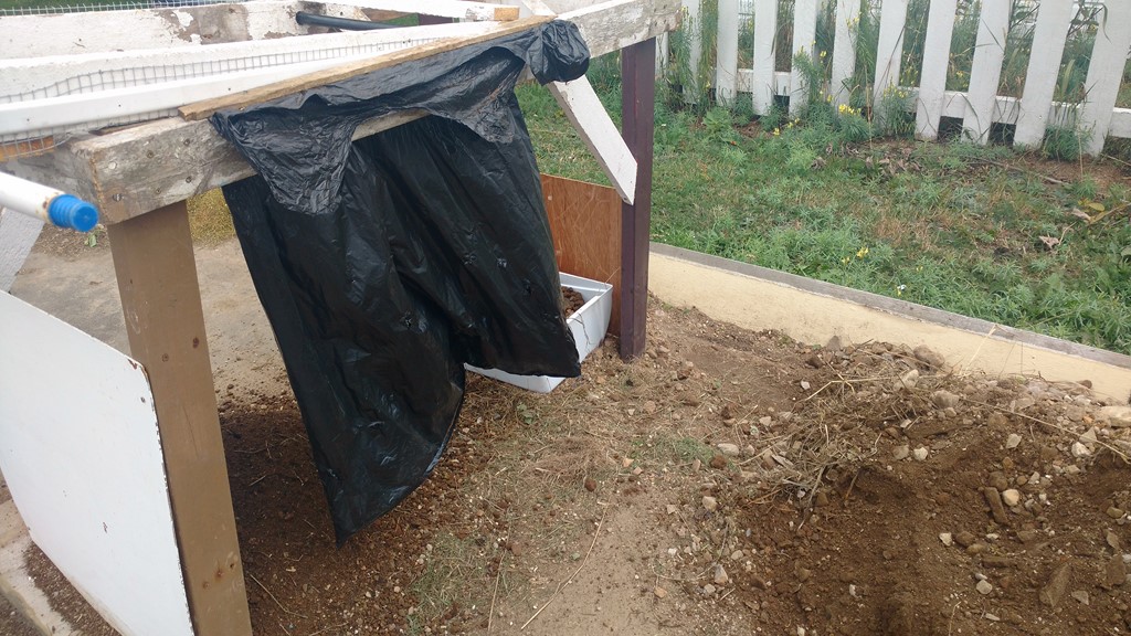
A trial skirt to reduce the amount of windblown fine soil.
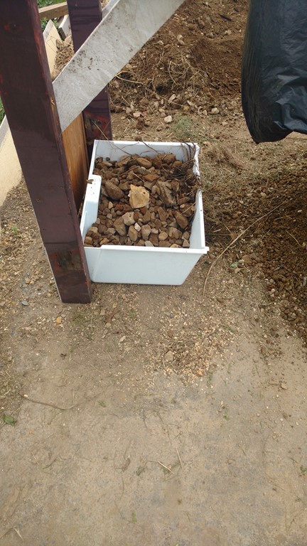
Another box of rocks.
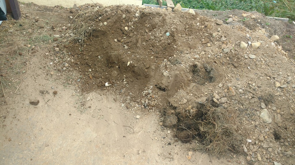
And I am making progress working through Danny's spoil.
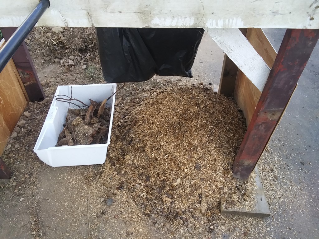
I made a replacement sawdust sieve with finer chicken wire - about one-inch, replacing the two-inch. I had to lift chunks of bark manually, but the sawdust is now being mixed with the soil, which makes for easier handling into the compost bins.
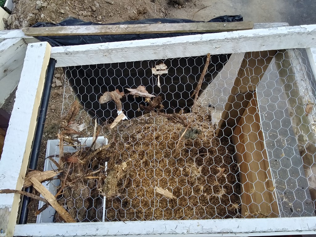
Not all the coarse material drifts down the sieve; twigs get caught in the mesh, so there needs to be periodic scraping. How will this impact a rotary sieve?
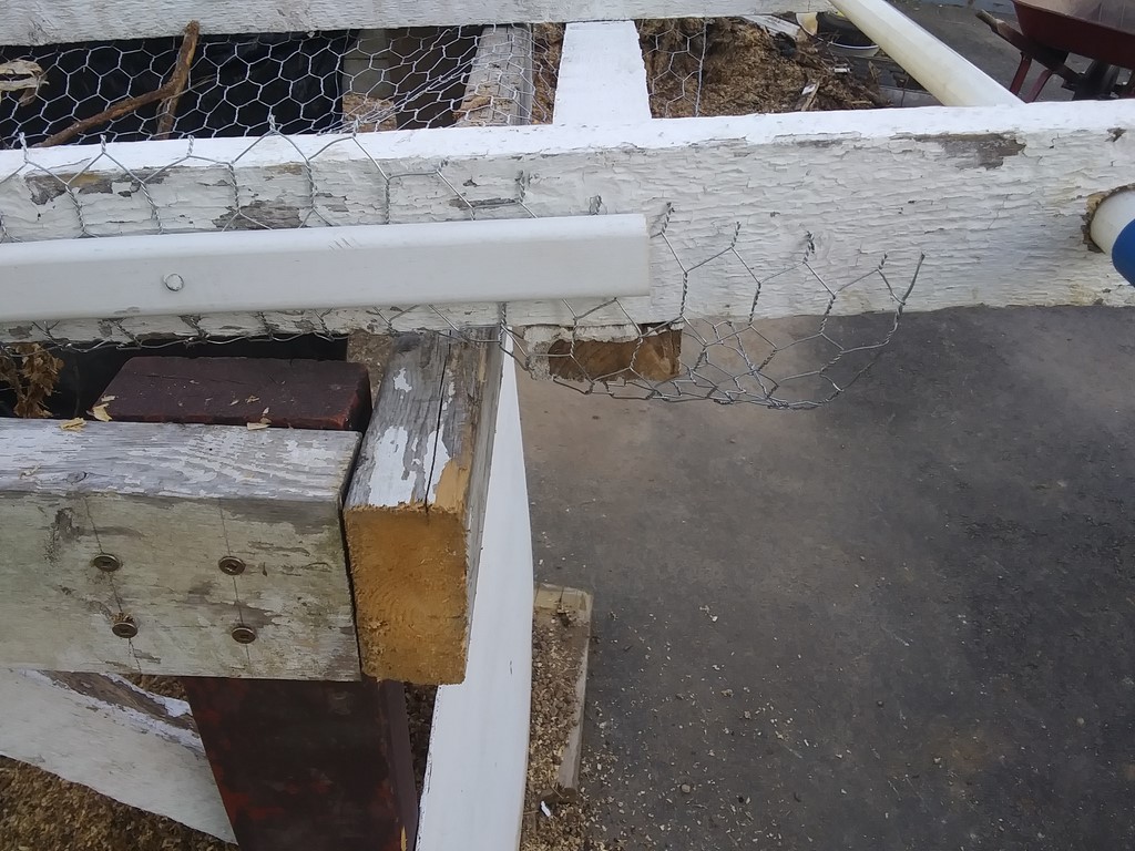
As well, I misplaced the mesh. There is a useless length of mesh up near the handle ...
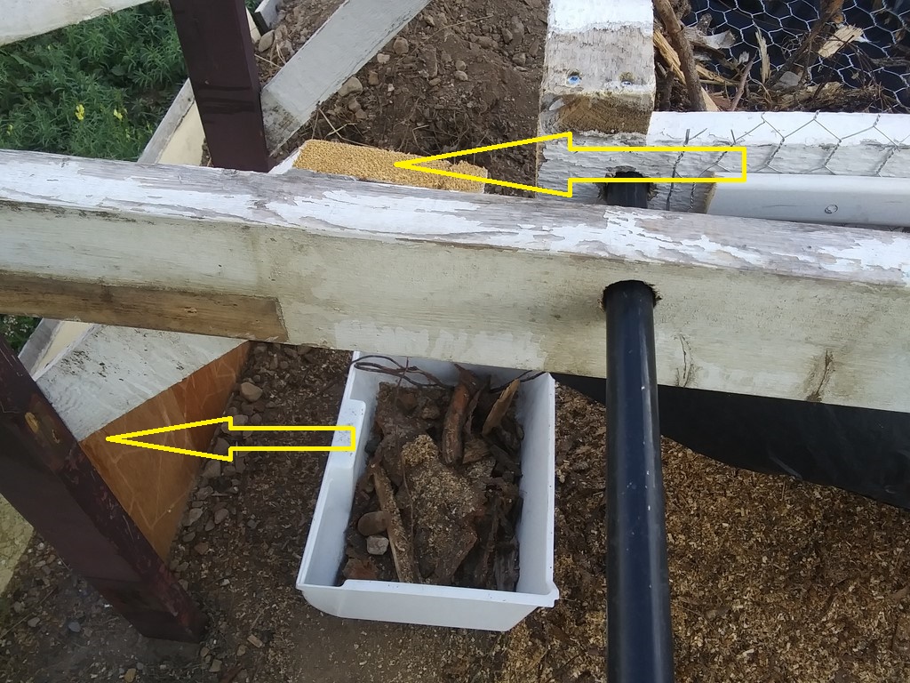
... and not enough mesh to reach the box. I moved the box closer for this first trial
Thursday, September 01, 2022
I carted four barrows of soil-mix to the compost bins, topping off the first three bins.
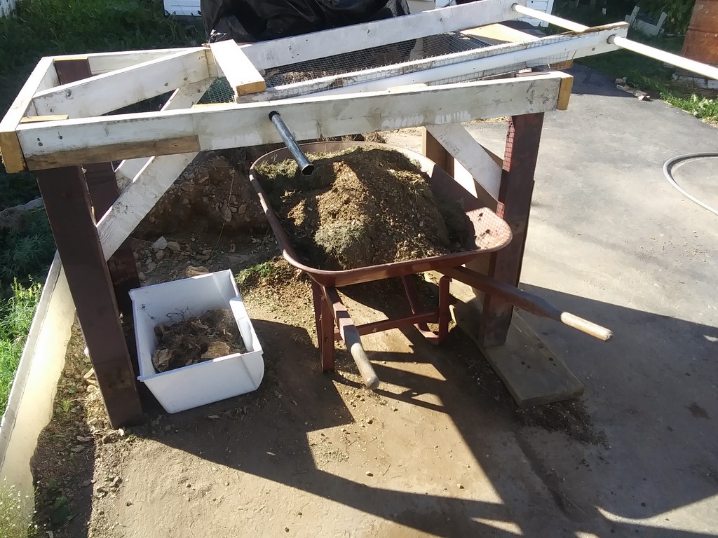
The wheel barrow is half-filled with grass; on top of that the remaining soil-mix from last night. The barrow is ready to receive sawdust or soil, whichever I do next.
I have moved the sieve about three feet southward, an indication of how much material I have processed this past week.
709-218-7927 CPRGreaves@gmail.com Bonavista, Thursday, September 26, 2024 8:36 AM Copyright © 1990-2024 Chris Greaves. All Rights Reserved. |
|---|